Search results
Search for "phase-locked loop" in Full Text gives 28 result(s) in Beilstein Journal of Nanotechnology.
Dual-heterodyne Kelvin probe force microscopy
Beilstein J. Nanotechnol. 2023, 14, 1068–1084, doi:10.3762/bjnano.14.88

- signal (or lock-in internal oscillator) is set to ω1, ultimately it will be used for signal demodulation. The second source signal is obtained by tracking the cantilever resonance frequency at its first eigenmode (ω0 + Δω0) with a second oscillator configured as a phase-locked loop (PLL). This tracking


High–low Kelvin probe force spectroscopy for measuring the interface state density
Beilstein J. Nanotechnol. 2023, 14, 175–189, doi:10.3762/bjnano.14.18

- measured using the displacement detection system was controlled by an automatic gain control (AGC) circuit to keep the cantilever vibration amplitude A constant, and the frequency shift Δf of the cantilever was measured using a phase-locked loop (PLL) circuit (SPECS GmbH: Nanonis OC4). AFM measurements


A cantilever-based, ultrahigh-vacuum, low-temperature scanning probe instrument for multidimensional scanning force microscopy
Beilstein J. Nanotechnol. 2022, 13, 1120–1140, doi:10.3762/bjnano.13.95

- macroscopic wire tip to the free prong. Compared to the typically used microscopic AFM cantilevers, the tuning fork sensor has a rather high stiffness, k ≈ 2 kN/m. This facilitates AFM operation with small oscillation amplitudes (A < 100 pm) because a snap-to-contact or instabilities of the phase-locked loop
- mechanical resonance, leading to a failure of the phase-locked loop to track the cantilever’s resonance frequency [53][56]. In such a case, optical excitation is preferred. In contrast to the mechanically excited cantilever (Figure 8b), an optical excitation (Figure 8c) leads to clean harmonic oscillator
- must be stored in the cantilever oscillation such that stochastic energy loss events caused by stochastic position changes of the tip apex [63] or sample atoms in interaction with the tip will not unlock (crash) the phase-locked loop. To obtain an oscillation energy of a few tens of electronvolts at


Two dynamic modes to streamline challenging atomic force microscopy measurements
Beilstein J. Nanotechnol. 2021, 12, 1226–1236, doi:10.3762/bjnano.12.90

- frequency fr. This frequency shift is proportional to the force gradient and has a nonmonotonic dependence on z [4][12][13][14]. This dependence can be directly observed if resonance conditions are maintained, for example, if we use a phase-locked loop and constantly keep the driving frequency at resonance
- of new modes. No new electronic elements are required (i.e., oscillators, integrators, or phase-locked loop systems), these tasks are carried out by the software. The introduction of the described techniques into standard AFM control programs is not very difficult, but can significantly simplify


Measurement of electrostatic tip–sample interactions by time-domain Kelvin probe force microscopy
Beilstein J. Nanotechnol. 2020, 11, 911–921, doi:10.3762/bjnano.11.76

- conventional frequency-modulated (FM-) KFM, the contributions at ωm and 2ωm are detected via lock-in techniques, either at the Δf output of a phase-locked loop (PLL) [12] or by detecting the sidebands of the cantilever oscillation [13]. In closed-loop FM-KFM, a feedback loop is employed to nullify the


Review of time-resolved non-contact electrostatic force microscopy techniques with applications to ionic transport measurements
Beilstein J. Nanotechnol. 2019, 10, 617–633, doi:10.3762/bjnano.10.62

- a phase-locked loop (PLL). This was first performed by Bennewitz et al. to measure the mobility of F− vacancies in a CaF2 crystal [27]. Schirmeisen et al. later improved the technique by performing the measurements at various temperatures to extract the activation energy for ionic transport in Li


In situ characterization of nanoscale contaminations adsorbed in air using atomic force microscopy
Beilstein J. Nanotechnol. 2018, 9, 2925–2935, doi:10.3762/bjnano.9.271

- the measured properties of the tip–sample system can be uniquely attributed to the sample. Experimental AFM data acquisition and processing AFM imaging Data was acquired using dynamic atomic force microscopy (DAFM) on a Nanotec Electronica AFM system with a phase-locked loop board (PLL, bandwidth ca


Quantitative comparison of wideband low-latency phase-locked loop circuit designs for high-speed frequency modulation atomic force microscopy
Beilstein J. Nanotechnol. 2018, 9, 1844–1855, doi:10.3762/bjnano.9.176

- dissolution process; frequency modulation atomic force microscopy; high-speed atomic-resolution imaging; phase-locked loop; Introduction Frequency modulation atomic force microscopy (FM-AFM) is a powerful tool for investigating atomic- and molecular-scale structures of sample surfaces in various environments
- improvements in bandwidth or resonance frequency of all of the components constituting the tip–sample distance regulation loop, such as the cantilever, cantilever excitation unit, cantilever deflection sensor, scanner, feedback controller, and phase-locked loop (PLL) circuit. In particular, the PLL circuit is
- Kazuki Miyata Takeshi Fukuma Nano Life Science Institute (WPI-NanoLSI), Kanazawa University, Kakuma-machi, Kanazawa 920-1192, Japan Division of Electrical Engineering and Computer Science, Kanazawa University, Kakuma-machi, Kanazawa 920-1192, Japan 10.3762/bjnano.9.176 Abstract A phase-locked


Correlative electrochemical strain and scanning electron microscopy for local characterization of the solid state electrolyte Li1.3Al0.3Ti1.7(PO4)3
Beilstein J. Nanotechnol. 2018, 9, 1564–1572, doi:10.3762/bjnano.9.148

- mobility [22]. As cantilevers, Bruker SCM-PIT-V2 (Bruker, Camarillo, USA) cantilevers with a conductive Pt/Ir coating and a nominal spring constant of 3 N·m−1 were employed. The contact resonance frequency and the amplitude were tracked with a phase-locked loop (HF2LI, Zurich Instruments, Switzerland) [34


Noise in NC-AFM measurements with significant tip–sample interaction
Beilstein J. Nanotechnol. 2016, 7, 1885–1904, doi:10.3762/bjnano.7.181
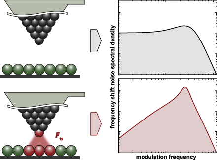
- between the amplitude and tip–sample distance control loops of the NC-AFM system as well as by the characteristics of the phase locked loop (PLL) detector used for frequency demodulation. Here, we measure DΔf(fm) for various NC-AFM parameter settings representing realistic measurement conditions and
- demodulator (mostly a phase-locked loop detector, PLL), cantilever properties and ultimately thermal noise [11]. The footing of our work are these precursor studies, and the rigorous system analysis introduced by Polesel-Maris et al. [12], showing that the frequency shift noise at close tip–sample distance is
- increased due to a coupling of the phase-locked loop with the amplitude and the distance control loops. While noise in the amplitude control loop itself is essentially independent of the frequency shift noise without tip–sample interaction, amplitude and topography feedback loop noise are coupled into the


![[Graphic 32]](/bjnano/content/inline/2190-4286-7-181-i73.png?max-width=637&scale=1.18182) wit...
wit...

![[Graphic 34]](/bjnano/content/inline/2190-4286-7-181-i75.png?max-width=637&scale=1.18182) wit...
wit...


Customized MFM probes with high lateral resolution
Beilstein J. Nanotechnol. 2016, 7, 1068–1074, doi:10.3762/bjnano.7.100

- MFM data correspond to the shift in the resonance frequency of the cantilever recorded during the retrace scan (withdrawing the sample by 10–20 nm from the topographic set point distance) by using a phase locked-loop (PLL) feedback. The topography and the magnetic properties of the reference Co/Si


Generalized Hertz model for bimodal nanomechanical mapping
Beilstein J. Nanotechnol. 2016, 7, 970–982, doi:10.3762/bjnano.7.89

- , where the resonance frequency fc is tracked with a phase-locked-loop (PLL), the measured frequency shift Δf can be used to estimate the interaction stiffness by the approximation In this mode, the oscillation amplitude is held constant with an AGC. The use of an AGC will be assumed for “FM mode
- amplitude Ar1 (free amplitude), the three configurations (AM-AM, AM-PM, AM-FM) yield the same results within error. Note that a value of Eeff was only extracted for values A1/Ar1 < 0.75 to ensure that repulsive interactions dominate. Using an automatic-gain-controller (AGC) and/or phase-locked-loop (PLL) to


![[Graphic 4]](/bjnano/content/inline/2190-4286-7-89-i40.png?max-width=637&scale=1.18182) approximation applied to Equation 6 i...
approximation applied to Equation 6 i...


Efficiency improvement in the cantilever photothermal excitation method using a photothermal conversion layer
Beilstein J. Nanotechnol. 2016, 7, 409–417, doi:10.3762/bjnano.7.36

- coated cantilevers were corrected by subtracting the frequency-dependent phase delay caused by a phase-locked loop circuit. The dotted lines in the figures show ideal phase curves calculated with resonance frequency (f0) and Q-factor estimated from cantilever thermal vibration spectra as shown in Table 1
- commercially available phase-locked loop circuit (OC4, SPECS, Zürich, Switzerland). A commercially available AFM controller (ARC2, Asylum Research, Santa Barbara, CA, USA) was used for the tip–sample distance feedback regulation and acquisition of FM-AFM images. The FM-AFM imaging of a mica surface was


Kelvin probe force microscopy for local characterisation of active nanoelectronic devices
Beilstein J. Nanotechnol. 2015, 6, 2193–2206, doi:10.3762/bjnano.6.225

- . Nevertheless, the averaging effect of the cantilever beam remains (see below in Figure 1). An alternative approach typically applied in vacuum is based on frequency modulation [15]. To this end, the frequency of the cantilever is usually tracked by a phase-locked loop (PLL). Its output signal, the frequency
- frequency (e.g., with a phase-locked loop) is merely to keep the carrier phase constant, which would otherwise affect the sideband phases. Electrostatic force and force gradient The electrostatic force between the AFM tip and sample is where is the effective capacitance gradient, Uts is the tip–sample


![[Graphic 33]](/bjnano/content/inline/2190-4286-6-225-i48.png?max-width=637&scale=1.18182) for different modulation amplitu...
for different modulation amplitu...


A scanning probe microscope for magnetoresistive cantilevers utilizing a nested scanner design for large-area scans
Beilstein J. Nanotechnol. 2015, 6, 451–461, doi:10.3762/bjnano.6.46

- tracked with a phase-locked-loop (PLL) while its frequency shift was used as a feedback for the topography feedback loop [6]. As the frequency tracking loop feeds back the cantilevers resonance frequency to the driving signal at a 90°phase shift, the contrast in the phase signal disappears as shown Figure


High-frequency multimodal atomic force microscopy
Beilstein J. Nanotechnol. 2014, 5, 2459–2467, doi:10.3762/bjnano.5.255

- simultaneously tracking topography. The resonant excitation power needed to keep the second eigenmode at a specific amplitude is mapped, while a phase locked loop (PLL) ensures resonant excitation. Topography feedback deconvolutes material specific effects acting on the second resonance. As the resonant


Impact of thermal frequency drift on highest precision force microscopy using quartz-based force sensors at low temperatures
Beilstein J. Nanotechnol. 2014, 5, 407–412, doi:10.3762/bjnano.5.48

- amplifier [26]. Finally, the frequency shift was determined by a digital phase locked loop stabilized by an oven-controlled quartz resonator with a precision of 1 ppb/day [27]. For the measurements, the temperature setpoint was increased at a rate of 0.5 K/min and the change in eigenfrequency was monitored


Challenges and complexities of multifrequency atomic force microscopy in liquid environments
Beilstein J. Nanotechnol. 2014, 5, 298–307, doi:10.3762/bjnano.5.33

- able to obtain an image with open loop drive of the higher mode. However, the implementation of FM requires either a phase-locked loop (PLL) or time delay (phase shifting), both of which are more complex and highly sensitive to perturbations. The time delay version of FM is even more susceptible to


Frequency, amplitude, and phase measurements in contact resonance atomic force microscopies
Beilstein J. Nanotechnol. 2014, 5, 278–288, doi:10.3762/bjnano.5.30

- cantilever dynamics, as well as the different effect of the tip–sample contact properties on those observables in each configuration are discussed. Finally, the expected accuracy of CR-AFM using phase-locked loop detection is investigated and quantification of the typical errors incurred during measurements
- is provided. Keywords: contact-resonance AFM; dynamic AFM; frequency modulation; phase-locked loop; viscoelasticity; Introduction A number of atomic force microscopy (AFM) variants have emerged since the introduction of the original technique in 1986 [1]. Besides topographical acquisition and
- phase) for the two cases, which require careful analysis for proper experimental setup and interpretation. As an example, we analyzed the errors introduced during resonance frequency tracking through the use of a phase-locked loop (PLL), which leads to different results in both configurations. This is a


Noise performance of frequency modulation Kelvin force microscopy
Beilstein J. Nanotechnol. 2014, 5, 1–18, doi:10.3762/bjnano.5.1

- Heinrich Diesinger Dominique Deresmes Thierry Melin Institut d’Electronique, Microélectronique et Nanotechnologie (IEMN), CNRS UMR 8520, CS 60069, Avenue Poincaré, 59652 Villeneuve d’Ascq, France 10.3762/bjnano.5.1 Abstract Noise performance of a phase-locked loop (PLL) based frequency modulation
- (proportional, integral) amplifier with the following response FPLL: The controller software automatically sets the time constant of the phase locked loop PI amplifier equal to the time constant of the phase detector lowpass function, τPLL = 2Q/2πf0, and the P gain such that the crossing with the forward gain


Determining cantilever stiffness from thermal noise
Beilstein J. Nanotechnol. 2013, 4, 227–233, doi:10.3762/bjnano.4.23

- spectral density (fm) in the frequency shift signal Δf(t), the spectrum analyser is connected to the phase-locked-loop (PLL) demodulator output of the respective NC-AFM system. In all of these experiments, utmost care has to be taken to shield the NC-AFM system from mechanical and, specifically, from

![[Graphic 34]](/bjnano/content/inline/2190-4286-4-23-i40.png?max-width=637&scale=1.18182) measured for the fundamental mode of cantilever V 4. Measureme...
measured for the fundamental mode of cantilever V 4. Measureme...


![[Graphic 23]](/bjnano/content/inline/2190-4286-4-23-i29.png?max-width=637&scale=1.18182) measured for cantilever V 4 (A0 = 16.8 nm, demodulator band...
measured for cantilever V 4 (A0 = 16.8 nm, demodulator band...
Bimodal atomic force microscopy driving the higher eigenmode in frequency-modulation mode: Implementation, advantages, disadvantages and comparison to the open-loop case
Beilstein J. Nanotechnol. 2013, 4, 198–207, doi:10.3762/bjnano.4.20

- provides information and guidelines that can be useful in selecting the most appropriate operation mode to characterize different samples in the most efficient and reliable way. Keywords: amplitude-modulation; atomic force microscopy; frequency-modulation; phase-locked loop; spectroscopy; Introduction
- scheme of the AM-FM mode Figure 1 shows a diagram of the experimental setup used, which consists of a commercial AFM system (MFP3D with ARC2 controller, Asylum Research Corporation, Santa Barbara, CA, USA) equipped with external phase-locked loop (PLL) electronics (PLL Pro 2, RHK Technology, Troy, MI
- amplitudes and phase shifts at each eigenmode of the cantilever. In contrast, the CE version of AM-FM requires either a phase-locked-loop (PLL) or a self-excitation (phase-shift-based) loop to keep the phase locked at 90 degrees (so far we have observed that self-excitation loops are less stable in tapping


Thermal noise limit for ultra-high vacuum noncontact atomic force microscopy
Beilstein J. Nanotechnol. 2013, 4, 32–44, doi:10.3762/bjnano.4.4

- commonly performed by a phase-locked loop (PLL) circuit [2]. As schematically depicted in Figure 1, the amplitude response of the PLL unit can formally be decomposed into the amplitude response Gdemod of the demodulator and the amplitude response Gfilter of an in-loop or output filter. The characteristics


![[Graphic 53]](/bjnano/content/inline/2190-4286-4-4-i64.png?max-width=637&scale=1.18182) =
= ![[Graphic 32]](/bjnano/content/inline/2190-4286-4-4-i43.png?max-width=637&scale=1.18182) f...
f...


![[Graphic 56]](/bjnano/content/inline/2190-4286-4-4-i67.png?max-width=637&scale=1.18182) using three diff...
using three diff...

Drive-amplitude-modulation atomic force microscopy: From vacuum to liquids
Beilstein J. Nanotechnol. 2012, 3, 336–344, doi:10.3762/bjnano.3.38

- the driving force as the feedback variable for topography. Additionally, a phase-locked loop can be used as a parallel feedback allowing separation of the conservative and nonconservative interactions. We describe the basis of this mode and present some examples of its performance in three different
- constant by adjusting the amplitude of the driving force. A phase-locked loop (PLL) tracks the effective resonance frequency of the cantilever as it varies as a consequence of the tip–sample interaction. In FM, the position of the scanner in the z-direction is adjusted to keep the frequency shift constant


Graphite, graphene on SiC, and graphene nanoribbons: Calculated images with a numerical FM-AFM
Beilstein J. Nanotechnol. 2012, 3, 301–311, doi:10.3762/bjnano.3.34

- dynamic behavior of the oscillator. Briefly speaking, an important element of the FM-AFM experimental apparatus is the frequency detection by demodulation performed with the aid of a phase-locked loop (PLL). This allows measurement of the frequency shift Δf from the fundamental resonance frequency of the


